DC-Digital Display Maintenance Guide for DB2 Board Removal & Installation for Manufacturing Users
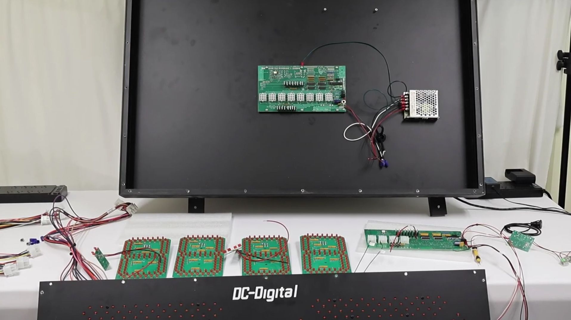
One of the advantages of DC-Digital display systems is their serviceability. In the unlikely event that a control board requires replacement, customers can often perform the repair themselves with basic hand tools and careful attention to wiring connections. This helps minimize downtime and allows critical clock, temperature, and information displays to return to operation quickly.
In this guide, we walk through the process of replacing a DB2 control board in a large DC-Digital display. While the demonstration shown in the video uses a smaller display for convenience, the same wiring concepts and installation procedures apply to many of our larger digital clock and temperature display systems.
Accessing the Display Electronics
The first step is gaining access to the display’s internal electronics. Begin by removing the screws around the perimeter of the display enclosure. Once the cover is removed, several digit connectors and indicator wiring connections will be visible.
Before disconnecting anything, it is highly recommended to take detailed photographs of the internal wiring configuration. These photos can serve as a valuable reference during reassembly and help eliminate guesswork when reconnecting components.
After documenting the wiring, disconnect the digit connectors, colon assemblies, decimal indicators, and any other connected wiring. Once these connections have been removed, the display face can be carefully set aside in a safe location while work is performed on the control board.
Removing the Existing DB2 Board
The DB2 board is secured inside the enclosure using mounting screws and a grounding connection. Begin by removing the grounding screw and strap connected to the board. Next, remove the remaining mounting screws securing the board to the enclosure.
Once the mounting hardware is removed, disconnect the power wiring and any communication wiring connected to the board.
Depending on the display configuration, power wiring may be connected directly to the board or routed through the power supply. In many cases, disconnecting the power leads at the power supply is the simplest method and helps avoid unnecessary cutting or splicing of wires.
Installing the Replacement Board
With the original board removed, the replacement DB2 board can be installed into the enclosure.
Position the new board and secure it using the mounting hardware. When tightening screws, care should be taken to avoid excessive torque that could damage the circuit board.
One of the most important steps during installation is reconnecting the grounding strap. This grounding connection helps protect the display from electrical surges and lightning-related events. Failure to reconnect the grounding strap could leave the display vulnerable to damage.
After securing the grounding connection, reconnect the positive and negative power wiring to the board. Always verify that wire colors match the original installation. Reversing polarity can damage electronic components and cause system failures.
Reconnecting Colon and Decimal Indicators
Many DC-Digital displays utilize colon and decimal indicators to provide additional information and status feedback.
The wiring for these indicators typically consists of dedicated hot and ground connections for both the colon and decimal assemblies. During installation, matching the original wire configuration is critical.
When reconnecting these components:
- Verify all wire connections before securing them.
- Ensure wire nuts or connectors are properly tightened.
- Confirm all indicator wiring matches the original configuration.
- Check that connections cannot pull loose during operation.
Properly wired indicator assemblies ensure reliable operation and accurate display functionality.
Connecting the Digit Displays
The digit displays connect to the DB2 board through dedicated connectors labeled according to their position within the display.
During installation, each digit connector should be reconnected to its corresponding location on the board. The connectors are designed to simplify installation while ensuring proper communication between the board and the LED digit modules.
Before powering the display, verify that all digit connectors are fully seated and securely attached.
GPS and Temperature Sensor Connections
Some display systems incorporate GPS synchronization, temperature monitoring, or both. These systems utilize interface boards that communicate directly with the DB2 board.
When reconnecting these accessories, match wire colors exactly:
- Red to red
- Black to black
- White to white
Proper communication wiring ensures accurate GPS synchronization and temperature readings after installation is complete.
If your display does not include GPS functionality, some of these connections may not be present. However, the overall installation process remains largely the same.
Power-Up and Verification
After all wiring connections have been completed, the display can be powered on for testing.
During startup, verify:
- All LED digits illuminate properly.
- Colon indicators function correctly.
- Decimal indicators operate as expected.
- Temperature readings display accurately.
- GPS synchronization functions normally if equipped.
- No error indicators are present.
A successful startup confirms that the replacement board has been installed correctly and that all display functions have been restored.
Troubleshooting Tips for a Successful Installation
The most valuable troubleshooting tip is also the simplest: take pictures before disconnecting anything.
Clear photographs of every wiring connection can dramatically reduce installation time and help identify any wiring mistakes during reassembly.
Additional recommendations include:
- Label wires before disconnecting them.
- Verify wire colors before making connections.
- Double-check all grounding connections.
- Confirm digit connectors are installed in the correct positions.
- Inspect all wire nuts and terminal connections before powering the display.
Following these simple practices can help ensure a smooth replacement process and reduce the likelihood of installation errors.
Designed for Long-Term Serviceability
DC-Digital displays are engineered with maintainability in mind. By designing systems that allow component-level replacement, customers can often restore operation quickly without replacing an entire display assembly.
Whether the display is used for synchronized timekeeping, temperature monitoring, GPS-controlled operation, manufacturing processes, schools, government facilities, or industrial applications, a properly installed replacement DB2 board can return the system to reliable operation with minimal downtime.
For additional support, replacement components, and information about DC-Digital digital clocks, timers, counters, and temperature displays, contact DC-Digital directly.
See similar product: DC-802C-W-IN
See our tutorial video on YouTube
Visit DC-Digital website
Contact us to ask about our customized product!
No Comments